

Layout Database File Control: The Missing Link
Resources, white papers, articles
Layout Database File Control: The Missing Link
By Dr Philippe Morey-Chaisemartin & Frederic Brault
XYALIS, France.
Published in TechDesign Forum – May 31st 2018
As the exchange of layout descriptions between teams involved in modern integrated circuit (IC) development and production increase in terms of rate, value and size, the need for control and reliability increases as well. While regular integrity control –– cyclic redundancy checks, cryptographic hash functions and error correcting codes, for example –– can be used, they quickly show their limits.
As often happens, two teams simultaneously manipulate the same layout using different representations with proprietary, standard or semi-standard formats such as GDSII, MEBES, OASIS® and OASIS.MASK. Comparing two databases to check their differences is a complex and time-consuming process and requires one of the parties to possess both files. For security reasons, it is common to avoid transmitting unnecessary data to a partner.
A standard traceability process usually starts with the creation of a unique signature that will accompany the transfer of a product, ensuring the recipient will be able to guarantee the authenticity of the received product. A good traceability system must be reliable and secure and independent of any specific implementation to ensure interoperability between heterogeneous environments. And, it must avoid leaking information about what it is protecting.
I. STATE OF THE ART
Not much exists on the market today to address these needs. Legacy formats such as GDSII or MEBES offer no integrity control. Newer formats like OASIS® include, as an option, a cyclic redundancy check (CRC) checksum, but have several drawbacks:
- The use of the CRC algorithm turns reading and writing into a linear operation –– bytes of the file have to be read in order –– disabling optimizations based on parallelism for large files.
- The CRC algorithm is an error-detection code and offers no security guarantee. For example, it is easy to create two files with different content, but the same CRC checksum.
- Since it is not mandatory, many writers omit checksum and some readers do not bother to check it.
Given all this, it is tempting to use other tools that are secure and efficient, including cryptographic checksums –– Secure Hash Algorithm (SHA) or the deprecated Message Digest 5 (MD5). Like the CRC checksum, they are byte-dependent, which means that a single bit change in the file is a dramatic change in the checksum. Normally, it would be considered a feature. For layout databases, it is a drawback because what needs to be secured and traced is not bytes in the file, but the actual design or geometric description.
The only way to check that two files implement the same geometric design is to run a exclusive OR (XOR) operation on them, a complex operation that takes time and requires expensive tools. Unlike a checksum, it requires the availability of the original file and the one needed for comparison. Users can’t easily know if the designs are the same, though that’s what they would like to do.
II. SPECIFIC CONSTRAINTS FOR LAYOUT FILE CONTROL
In most cases, checking and validating the contents of a file is important, not the container by itself. This becomes mandatory in the electronic design automation (EDA) process flow because of the various ways to describe the same thing. In addition to generic considerations on the file signature, microelectronics has specific needs and constraints.
On the design side, most layout files use the GDSII format, the de facto standard though some companies are switching to OASIS®. It’s a gradual transition because all EDA tools do not yet support the OASIS® format, which means the design back end flows need to manage both GDSII and OASIS files with some translation at defined steps.
Users are reluctant to switch due to a lack of quick and easy ways to verify that a layout description in OASIS® is the same as in GDSII, which makes providing a format independent signature necessary. Signing a layout described in GDSII and signing the same layout described in OASIS® must yield the same result, as for other formats such as OASIS.MASK or MEBES.
Most chip layout formats offer a great liberty on the description structure by itself. In GDSII, for example, the order of cells described in a file is totally arbitrary.
Even if lower-level polygon descriptions are identical and the hierarchies are identical, it is impossible to compare two files by using a file level signature. Reading a GDSII file within an EDA tool and rewriting it without modifications breaks the signature, considering that it also contains the creation date and other meta-data. This makes any checksum unusable. The problem is worse with OASIS® because the format offers a number of different ways to save the same data, including strict mode, by reference or by name. These non-geometric intricacies should not impact the signature.
The main geometric issue is that EDA tools and file formats allow different ways to describe the same thing. For example a “wire,” can be drawn as a “path,” i.e. a succession of butting segments with a given width or as a complex polygon that can be described as an assembly of basic trapezoids .
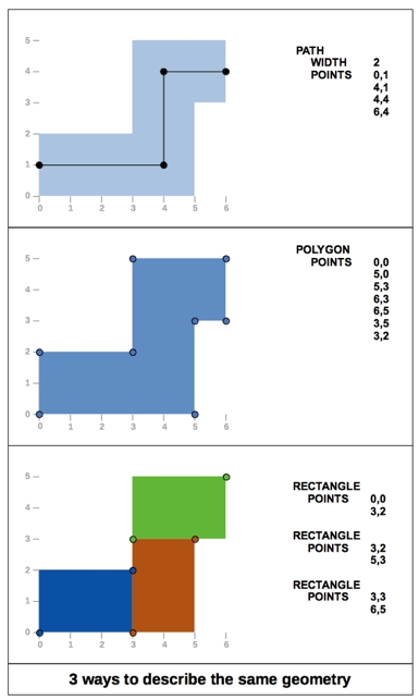
Figure #1: Different EDA tools and file formats allow different ways to describe the same geometry, as illustrated here.
Additionally, there is no constraint regarding the description of a polygon. It is a list of edges starting from one arbitrary point of the polygon and turning either clockwise or counter clockwise, making a classical signature of a simple polygon description irrelevant. If the user doesn’t care about polygon overlaps within the same layer, a meaningful signature must only consider the final envelope of the whole polygon with clear specifications on the vertex order.
When validating file integrity, a global checksum or signature is enough. Simple “go/no go” information is useless in most cases on a huge layout file and it is important to know the number of differences as well as their position. For example, when comparing two text files, using “diff” gives more information than using a simple checksum because users can know how many lines and which ones contain differences.
In the same way, a layout file can be split in windows to compare two files. Comparison will be made window by window. This makes it possible to run a more detailed “XOR” on reported windows, if needed. The same mechanism can be used for the signature. Instead of reporting a single checksum for the entire layout, the signature can be a list of checksums –– one for each window. The signature becomes a file containing the window information and the checksum for each window.
Chip layout description files generally contain multiple layers. When a rework is required on a chip, it is generally made with a metal fix where only a few interconnection layers are changed. This is a must to reduce mask cost and accelerate delivery time by using wafers already processed up to interconnection layers. For mask data preparation teams, it is important to quickly check that all front-end layers are strictly identical while only expected metal layers have been changed. The signature of a layout database must be split by layers.
After reviewing the specific needs of chip layout files, a list of constraints that should be met for an efficient signature strategy is in order. A signature file must validate content, not the container and must be:
- Independent of the file format and description strategy
- Based on the final geometric envelope of polygons
- Split in windows and layers
III. SOLUTION: A NEW SIGNATURE
It’s apparent from the list of constraints that a new signature standard for chip layout files is necessary. The standard must lead to a unique and universal way to sign any layout database. It will not be a single checksum, but a file containing checksums for each window and each layer, and contain additional information such as window size and column/row number.
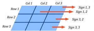
Figure #2: A new signature standard will offer a new way to sign any layout database.
As noted above, two identical layouts must give the same signature, despite the fact that description methods may differ. To get such a result, it is mandatory to define a unique way to describe the geometries –– more accurately, the geometrical envelope.
To guarantee its uniqueness, this description must meet multiple constraints such as defining an order for the vertices and defining precisely which points are part of the description. Then, using standard algorithms such as SHA256 or SHA3, the uniqueness of the signature of the description can be guaranteed.
The signature file will be small compared to the original database and used as a reference at any time. Comparison between two layout databases will not be made by a full XOR, but by comparing signatures of the two databases. It also will be possible to compare a database with a previously computed signature file.
With such a signature based on the geometrical description, any physical change of the layout will be quickly detected, whether accidental or intentional.
For example, as soon as a rework –– i.e. a metal fix –– is requested on a design, the new database is compared to the original to check that only expected layers have been changed, and usually only in a few localized areas. This is always time consuming and requires recovering the original database archive.
Using the signature file as a reference simplifies the process because it is small enough to be accessible. It also contains enough information to guarantee the similarity between some layers and highlight the windows where differences have been found on other layers. If needed, it will be possible to run a detailed XOR but only on windows containing differences.
Since the signature only depends on the physical layout, it is easy to check that a simple read/write with a tool or a format conversion such as GDSII to OASIS® has not made any geometric modification. And, because the signature will never change unless a geometrical transformation has been introduced in the layout, it is well suited for validating new tools and complex flows, such as hierarchy flattening or layer splitting.
IV. CONCLUSION
The proposed signature is tailor-made for layout database file integrity control. It is secure, reliable and, most important, focuses on what really matters –– the geometric description. It allows for quick and easy comparison of huge databases, based only on a small signature file that does not contain sensitive information and can be safely sent to any partner. Such a signature will have a positive impact on the semiconductor industry as an open standard. A fair use policy on the patent that covers the signature scheme will be enforced.
As an open standard, the signature becomes even more useful. It can be embedded directly into OASIS® or OASIS.MASK databases as a special property, for example.
-
Categories
- Glossary
- Publications
- Resources
- Whitepapers